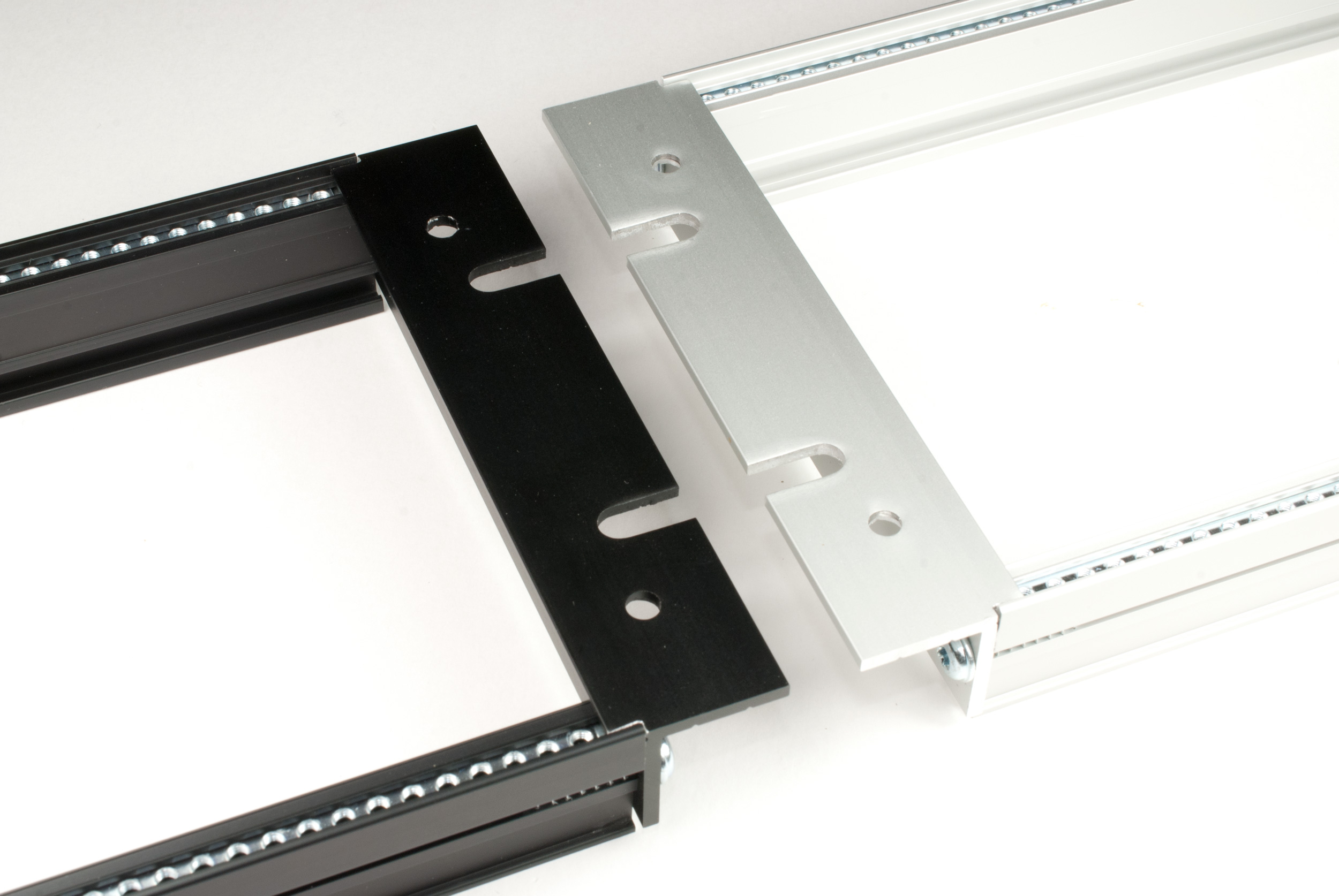
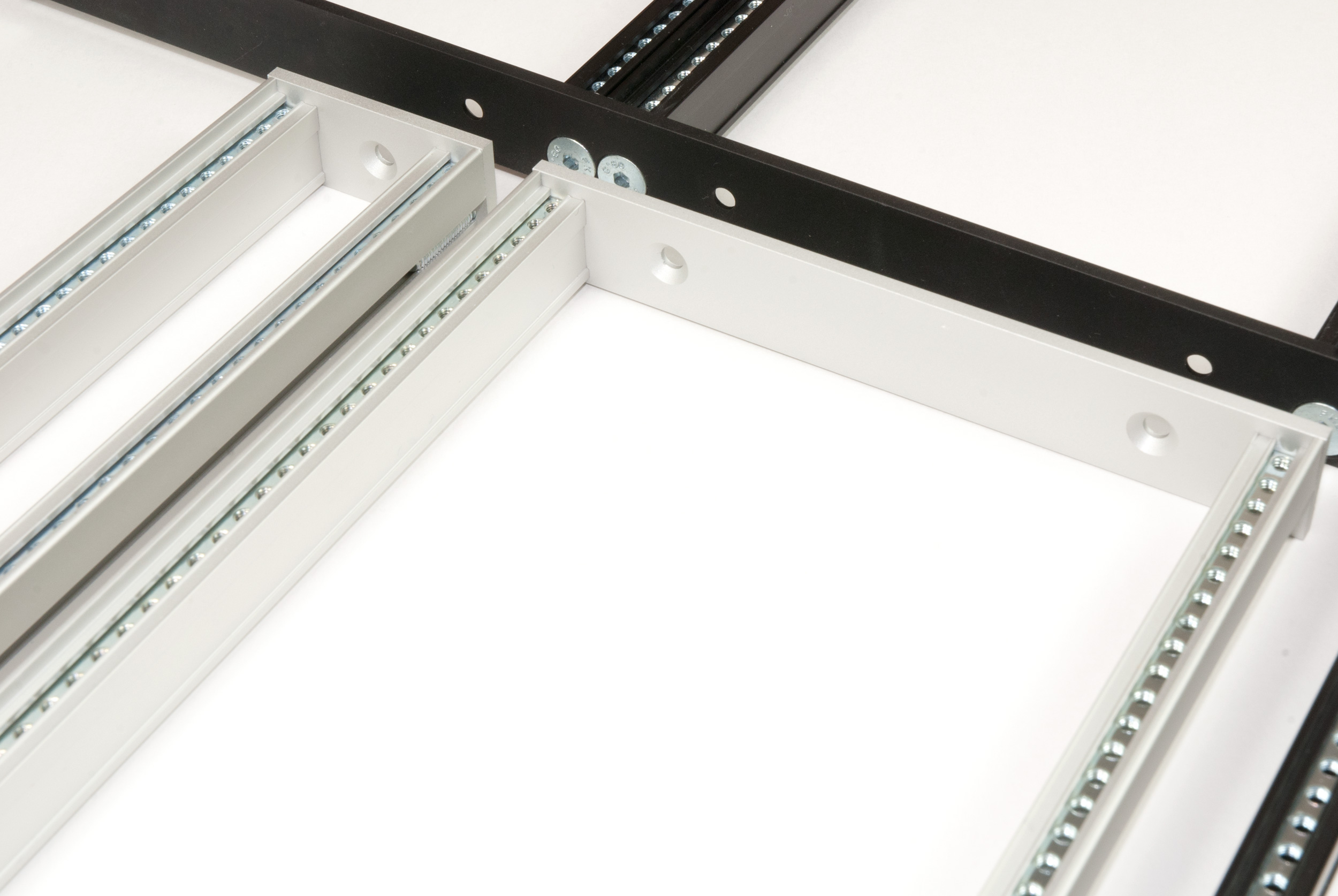
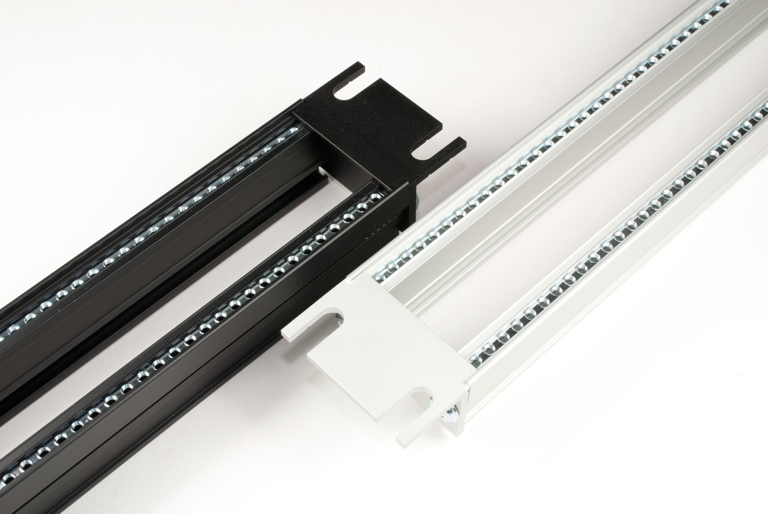

Today the PCBs arrived and I had to start soldering one immediately. You will notice that the layout is similar to the Doepfer PSU. I tried to develop a complete own board but I have to admit that the design is compelling. The circuit uses the LM 317 and 337 adjustable regulators, they deliver the +12V and -12V, a ringcore transformer, a bridge rectifier and a few other parts. I tried several layouts with this parts, but the Doepfer layout is the best. I think they perfected it over the years. I know that my board is a copy though but it was still a lot of research needed to get all the parts together and finally create the layout. As I will need at least four PSUs, I decided to let the boards be produced by a company. But this only makes sense if you order more than 10 or 20 pieces. So I might have some “in stock”…
First I have to finish my prototype to see if everything works as expected. Then I will order the parts for the “serial” production.
")
DIY: Creating a Eurorack-Case from scratch
This post was about the beginning of my DIY case journey. The next steps can be found in a more recent post as the journey continues.


If you want to read the full story, here are all the posts:
Triggering, Syncing and Programming
a Roland CR-78
Connecting the first programmable drum machine with an analogue modular synthesizer and using an 8-step sequenzer for programming it.
 One of the main things an owner of a Roland CR-78 wants to do is for sure to program it. Come on, it is the first programmable drum machine. So what would you do, playing the presets? Boring! When Roland started selling the machine in 1978 they also offered a manual switch (TS-1) and a writing switch (WS-1). The latter is an object of desire for most CR-78 owners. The price for a used unit is preposterous high. Yes, the WS-1 might make the programming easier, but you can invest the money better than just for this purpose. Ever thought about a modular synthesizer?
This post describes how you can achive the programming of the CR-78 with a modular synth, namely the Doepfer A-100. But of course buying a modular synth just for this job is absurd. If you prefer using MIDI there is a really good article working it out with a Kenton Pro Solo MkII and a Korg Electribe.
The modules used for this setup are:
- A-146 LFO II
- A-155 Analog/Trigger Sequencer
- A-160 Clock/Trigger Divider
- A-161 Clock/Trigger Sequencer
- A-180 Multiples
The price for this modules is round about 500 EUR without a case. There were people paying this price for a used WS-1 on eBay. Furthermore you will need a special cable which converts the gate signal to a switched trigger (S-Trig) signal. Whoever is able to handle a soldering iron should manage to fix the cable themselves. It is not a big deal and much cheaper, not more then 6 EUR each. You will need two of them.
Triggering
Some basics about the CR-78. If you read through the related threads on the web some people obviously tend to think you can easily trigger the machine with a simple click. Sorry chaps, it’s a bit more complicated. But never mind, we are on the way to solve it. The external clock input accepts a clock of 12 ppqn (pulses per quarter note), which adds up to 48 pulses per bar/measure on a four-four time. The signal should be between +5V to +15V, and have a length of min. 5ms. This is where the Doepfer A-146 LFO comes into play, it gives you exactly what you need, a +5V symmetric pulse wave. Just plug the output of the pulse wave into the external clock of the CR-78 and the machine should run with the clock generated by the LFO. You might have to adjust the pulse width, but that’s it. To check if it works just press the start/stop button of the CR-78 and once it runs adjust the frequency of the LFO. You should send the LFO signal into the A-180 Multiples to have it available for the CR-78 and the A-160 Clock Divider.
Syncing
Okay, this was the simple part. The CR-78 is now pulsed with 12 clocks per quarter node which is quite fast for a modular synthesizer to work with. Even if  you want to work on beats it might be too fast. We need to divide the clock of the LFO into a usable clock to trigger the A-155 Step Sequenzer to get prepared for the programming. Therefore we need the A-160 and A-161. The A-160 Clock Divider is needed to drive the A-161 Clock Sequencer which again is driving the A-155 and also resets the A-160 if the division of the clock is reached. Actually it is a simple patch but it sounds more complicated than it is.
The programming section of the CR-78 can save four patterns of two bars. Each pattern can save up to four different instruments. The machine is triggered with 12 ppqn which adds up to 96 clocks for the two bars. The A-161 Clock Sequencer triggers the clock of the A-155 with every 6th step. If you divide 96 by 6 you will get 16 steps, 8 steps for each bar. This is what the A-155 can perfectly handle. The A-161 needs to reset the A-160 after the 6th step, therefore you just patch a connection between step 7 (A-161) and the reset of the A-160. The A-155 should now run synchron with the CR-78. If you want more steps per bar then just trigger the A-155 after each 3rd step and reset the A-160 with the 4th step. This gives you 16 steps per bar. Programming is a bit more tricky though but with some practice you might get it done. With a second A-160 and an A-150 Voltage Controlled Switch you can change the A-155 into a 16-step sequencer.
 Programming

Now connect one of the trigger outputs of the A-155 with the start/stop jack of the Roland. Use the S-Trig cable for this. The CR-78 should start or stop when you toggle one of the switches. But toggle it back otherwise the machine stops with the next loop. The second S-Trig cable is used to program the machine, connect the gate output of the A-155 with the TS-1 jack of the Roland.
Now the fun begins. You have to select the instrument you want to program with the selector on the CR-78. Flip the “Program Switch” to “MEMORY”, on the A-155 flip the switches for the steps you want to trigger on the CR-78. Be aware that each program consists of two bars but we have only 8 steps to program at once. If you let the A-155 run through the two bars will be the same.